Programming ESP32 S2 Mini with ESP-IDF: Automatic Light Bulb Control
Introduction
In recent weeks, I've become quite interested in the world of electronics, specifically development boards like Arduino and ESP32. Taking advantage of the fact that my younger brother had a science project involving growing a plant in a dark environment and providing it with light via a lamp for 8 hours daily, I came up with the idea of using these development boards to automate the process and also to learn how to use the ESP32 S2 mini board. Therefore, this blog post will focus on programming the ESP32 S2 Mini with ESP-IDF for an IoT project.
Proposal
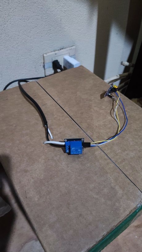
The system consists of an ESP32-S2 mini board connected to a relay that will control the power flow to the lamp. Since timed control is required to turn the light on or off, the board will need to connect to the internet to obtain the current time and synchronize its internal clock. This is necessary because these boards do not have an internal battery to keep the clock running when they are turned off, as is the case with computers and phones. A diagram is attached to aid understanding.
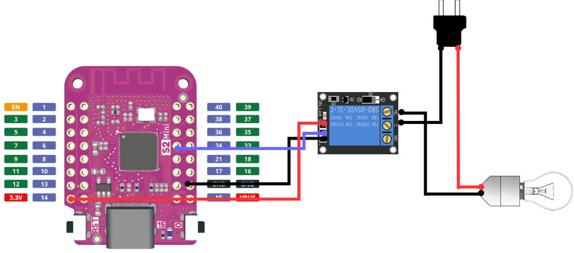
As can be seen in the diagram, the relay is connected to the 3.3-volt pin and ground in their respective positive and negative pins. The pin that controls the relay is connected to GPIO34. Then, in the relay, the current from the power grid is connected to the switch, and another cable exits from the NC port of the relay. This NC port stands for Normally Closed, as it will only supply power for 8 hours; the rest of the time, it should remain off.
Materials, Tools, and Necessary Technologies
- ESP32 S2 Mini
- Bulb
- Ceiling Fixture
- Relay Module
- Cables to connect the module with the board and the power with the bulb and the relay
- ESP-IDF installed (check the official ESP-IDF documentation for installation instructions)
- USB-C cable capable of transmitting data (some do not transmit data and are not suitable for flashing the image)
Creating the ESP-IDF Project for ESP32 S2 Mini
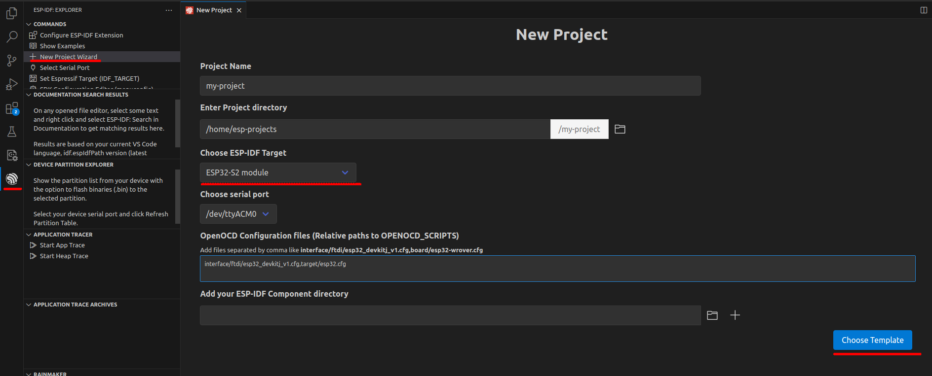
With the ESP-IDF extension configured in Visual Studio Code, select the extension and 'New Project Wizard' to begin creating the project. Once the new project screen is open, fill in the information on where the project will be located, project name, and board port.
NOTE: To make the port appear, before opening the new project creation screen, you must put the board in Device Firmware Upgrade mode. Simply hold down the
0button, then press theRSTbutton, and finally release the0button.
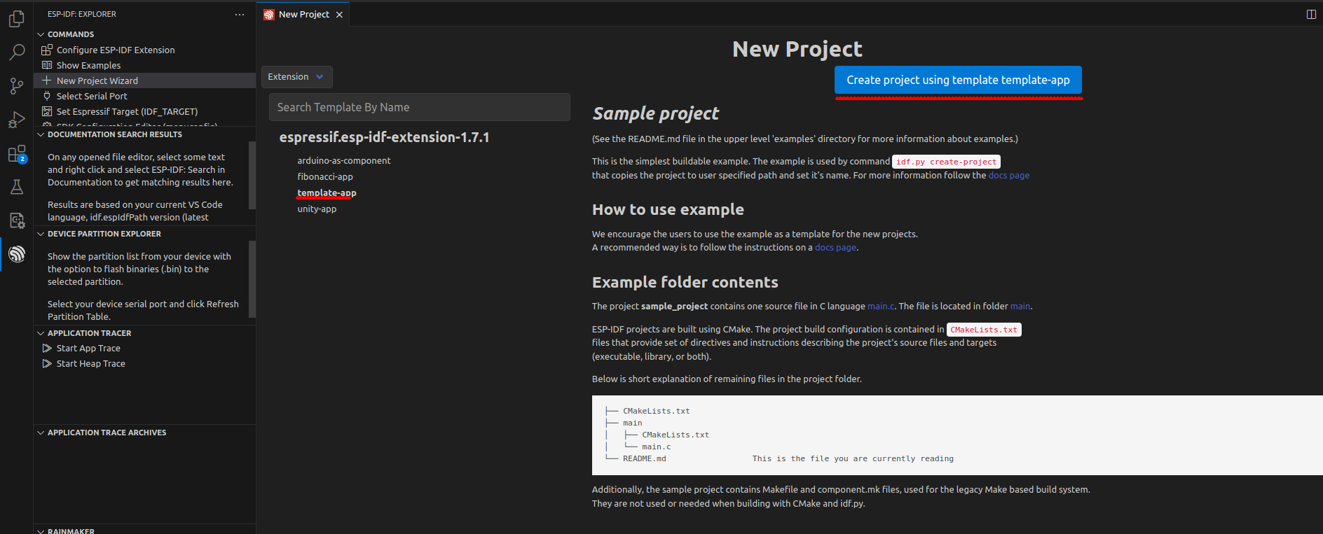
Proceed to select the project template. Choose the template-app template and create the project.
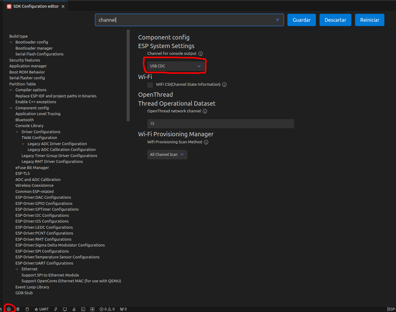
Once the project is created, there is one last task to do, which is to modify the console output channel. While developing the code for this project, I encountered the problem that the board displayed nothing when accessing the serial console. After doing some research on the Internet, I found this post on the ESP32 forum, which helped me solve this problem. The solution is simple: just go to menuconfig >> Component config >> ESP System Settings >> Channel for console output and select USB CDC.
Project Code
This section may be dense, so I'll provide a brief description of the code and attach a link to the repository of this project. I'll also provide a ZIP file of the project in case I decide to remove it from my GitHub.
The general structure of the project is as follows:
- components
- sntp_control
- sntp_control.c
- sntp_control.h
- wifi
- wifi.c
- wifi.h
- sntp_control
- main
- main.c
The file main.c is the entry point of the project and makes use of the WiFi and SNTP control modules. Its code is as follows:
    // import components
#include "wifi.h"
#include "sntp_control.h"

#include "esp_sleep.h"
#include "esp_system.h"
#include "esp_event.h"
#include "esp_log.h"
#include "nvs_flash.h"
#include "driver/gpio.h"

void init_gpio()
{
    // init the GPIO for Relay
    ...
}

void app_main(void)
{
    esp_err_t ret = nvs_flash_init();
    if (ret == ESP_ERR_NVS_NO_FREE_PAGES || ret == ESP_ERR_NVS_NEW_VERSION_FOUND)
    {
        ESP_ERROR_CHECK(nvs_flash_erase());
        ret = nvs_flash_init();
    }
    ESP_ERROR_CHECK(ret);

    init_gpio();
    init_wifi();
    if (!is_wifi_connected())
    {
       // restart the board
        ...
    }

    init_sntp();

    if (!is_sntp_sincronized())
    {
        // restart the board
        ...
    }

    stop_wifi(); // WiFi is not more require

    int current_hour = get_current_hour();

    stop_sntp(); // sntp is not more require

    if (current_hour < start_hour || current_hour >= end_hour)
    {
        // put on hibernation
        return;
    }

    // turn on the light
    ...
}
In the final part of the app_main function is where the process of checking if it is within the hours when it should be on or off occurs. If it should not be on, it enters Deep Sleep mode to save energy, and if it should be on, it activates the relay and suspends.
The components folder is responsible for storing the different modules of the project. In this case, we have the following:
The wifi component is responsible for initializing, configuring, and connecting to a WiFi network. Its code is as follows:
    #include "wifi.h"
    static void event_handler(void *arg, esp_event_base_t event_base,
                            int32_t event_id, void *event_data)
    {
        // handle the diferents events
        ...
    }

    void stop_wifi()
    {
        // Stop the wifi connection
        ...
    }

    void start_wifi()
    {
        // start new wifi connection
        ...
    }

    bool is_wifi_connected()
    {
        // return if connected to wifi
        ...
    }

    void init_wifi(void)
    {
        // configure the board to connect to the wifi
        ...
    }
The sntp_control component is responsible for synchronizing the board with the time obtained from an SNTP server. Its code is as follows:
    #include "sntp_control.h"

    struct tm get_current_time()
    {
        // Get the current board time
        ...
    }

    int get_current_hour()
    {
        // get the hour
        ...
    }

    int get_current_minute()
    {
        // get the current hour minute
        ...
    }

    void stop_sntp()
    {
        // stop the SNTP sincronization
        ...
    }

    void start_sntp()
    {
        // start the SNTP sincronization
        ...
    }

    bool is_sntp_sincronized()
    {
        //return if is sincronized
        ...
    }

    void callback(struct timeval *tv)
    {
        // this will called when the board was sincronized
        ...
    }

    void init_sntp(void)
    {
        // configure and start the SNTP
        ...
    }
Uploading Code to the Board
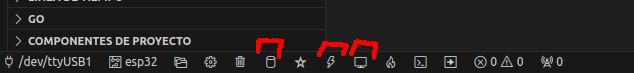
This is the simplest process. The ESP-IDF extension provides tools for compiling, uploading, and viewing the serial console. In the bottom bar, you can find the shortcuts. First, compile the project. Once compiled, proceed to upload the code, and then you can open the console to view the board's messages.
Conclusions
As a result, an automated system was obtained to turn on and off a bulb, with the aim of facilitating the execution of the scientific project. The board will turn on for 8 hours every day and turn off when not in use. The plant will be in darkness thanks to the box, while the bulb inside will provide the necessary light.